Trending Bit
Translate
- Get link
- X
- Other Apps
To draw the I - V characteristic curve for a Zener diode in reverse bias and hence to determine its breakdown voltage
ZENER DIODE CHARACTERISTICS
Zener diode is also known as the breakdown diode. It's been heavily doped with a silicon crystal diode designed to operate in the reverse direction. Hence it's known as the Zener diode. When the voltage across the terminals of a Zener diode is reversed, potential reaches the Zener voltage OR (Knee Voltage)
Clarence Zener, described the property concerning the breakdown of electrical insulators.
Aim of the experiment :
To draw the I - V characteristic curve for a Zener diode in reverse bias and hence to determine its breakdown voltage
Apparatus required :
- Connecting wires
- Zener Diode
- Micro Ammeter
- Voltmeter
- Rheostat
- Plug Key
- Battery
Principle of the experiment :
Zener Diode is a special-purpose diode designed to work in reverse bias. At the breakdown region, the reverse voltage remains constant for a large change in current. Thus Zener diode acts as a voltage regulator.
Circuit diagram :
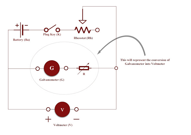
The circuit diagram for a Zener diode in reverse bias and hence to determine its breakdown voltage
 |
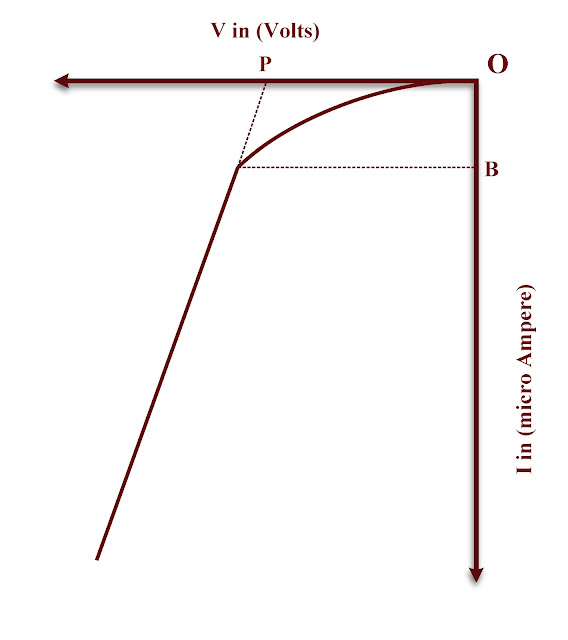
| I - V characteristic curve for a Zener diode in reverse bias |
Nature of Graph :
 |
| I - V characteristic curve for a Zener diode in reverse bias |
Procedure :
- The circuit is constructed as shown in the diagram.
- Rheostat is adjusted for a suitable value of voltage V. Corresponding value of I is noted.
- Voltage is increased in small steps and each time corresponding current value is tabulated.
- A graph is plotted with V along the negative X - axis and I along the negative Y - axis.
- Breakdown voltage is noted from the graph.
Observation :
Note down the observed values in the respective tabular column below.
| Trial No | V, in (Volts) | I, in (µA) |
|---|---|---|
| 01. | ||
| 02. | ||
| 03. | ||
| 04. | ||
| 05. | ||
| 06. | ||
| 07. | ||
| 08. | ||
| 09. | ||
| 10. | ||
| 11. | ||
| 12. | ||
| 13. | ||
| 14. | ||
| 15. |
Calculation :
01. From the graph, breakdown voltage, OP = ................................... volts
Result :
The breakdown voltage of the given diode, = ................................... volts
BITS ARROW
Popular Posts
How to change the capitalization or cases of selected texts in Microsoft word
- Get link
- X
- Other Apps
To convert the given galvanometer of known resistance and figure of merit into a voltmeter of desired range and to verify the same
- Get link
- X
- Other Apps
To determine the resistance of the given wire using a metre bridge and hence to find the resistivity of the material
- Get link
- X
- Other Apps
To determine the resistance of a galvanometer by half deflection method and to find its figure of merit of galvanometer
- Get link
- X
- Other Apps
How to enroll for 1st standard in SATS Portal (Student Achievement Tracking System)
- Get link
- X
- Other Apps


Comments
Post a Comment