FORWARD BIAS CHARACTERISTICS OF SEMICONDUCTOR DIODE
Semiconductors are materials that usually made of pure elements such as Germanium Silicon OR even compounds of Cadmium selenide OR am Gallium arsenide. Semiconductors have high conductivity between conductors and insulators. Genrally conductors are metals and non-conductors are insulators.
Semiconductors are classified into 2 types they are as follow below :
01. Intrinsic semiconductors : These are the semiconductors free from impurities or also called as undoped semiconductor or chemically pure. Semiconducting materials like Silicon and Germanium are the most common type of intrinsic semiconductors.
02. Extrinsic semiconductors : These are the semiconductors are produced by doping specific impurities. The process of adding impuritiy atoms to the pure semiconductor is called doping. Semiconducting materials like Silicon and Germanium are been doped with specific chemical impurities like As ,P ,Bi ,Al ,etc
Extrinsic semiconductors can be of 2 types they are P - type semiconductors & N - type semiconductors depending on the impurities added to it respectively. An semiconductor diode consist of the combination of P - type semiconductors & N - type semiconductors respectively.
Aim of the experiment :
To draw the I - V characteristic curve for P - N junction diode in forward bias and to determine the cut in voltage.
Apparatus required :
- Connecting wire
- Semiconductor diode
- Milliammeter
- Voltmeter
- Rheostat
- Battery
- Plug Key
Principle of the experiment :
When the positive terminal of the battery is connected to a P - side of the diode and the negative terminal of the battery is connected to an N - side, the diode is said to be forward-biased. Diode offers very low resistance during forward bias and current in the order of milliamperes flows through it.
Cut-in voltage is the characteristic voltage of the diode after which the current increases sharply during forward bias.
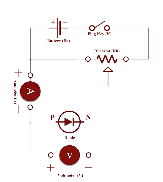
Circuit diagram :
The circuit diagram for P - N junction diode in forward bias and to determine the cut in voltage as follows below :
 |
| I - V characteristic curve for P - N junction diode in forward bias and to determine the cut in voltage |
Nature of the graph :
 |
| Graph of Voltage,V in (volts) Vs Current,I in (milli Ampere) |
Procedure :
- Circuit is constructed as shown in the figure respectively.
- Rheostat is adjusted for a suitable value of voltage V. Corresponding value of I is noted.
- Voltage is increased in small steps and each time corresponding value of current is tabulated.
- A graph is plotted with V along X - axis and I along Y - axis.
- Cut-in voltage is noted from the graph.
Observation :
Note down the observed values in the respective tabular column below.
| Trial No |
V, in (Volts)
|
I, in (mA)
|
| 01. |
|
|
| 02. |
|
|
| 03. |
|
|
| 04. |
|
|
| 05. |
|
|
| 06. |
|
|
| 07. |
|
|
| 08. |
|
|
| 09. |
|
|
| 10. |
|
|
| 11. |
|
|
| 12. |
|
|
| 13. |
|
|
| 14. |
|
|
| 15. |
|
|
Calculation :
01. From the graph, OP = ..............................Volts
Result :
The cut-in voltage of the given diode = ..............................Volts


%2016.jpg)


.png)
Comments
Post a Comment